|
|
(47 intermediate revisions by 4 users not shown)
|
| Line 1: |
Line 1: |
| | <languages /> | | <languages /> |
| | <translate><!--T:1--> | | <translate><!--T:1--> |
| − | This page explains how to build a pc to PS3/Xbox 360/PS4/Xbox One usb adapter.<br /> | + | This page explains how to build a GIMX DIY USB adapter.<br /> |
| | | | |
| | <!--T:22--> | | <!--T:22--> |
| | + | '''[https://blog.gimx.fr/shop/ Buy a ready to use GIMX adapter from the official GIMX shop.]'''<br /> |
| | '''A much easier but less complete tutorial is also available: [[DIY_USB_adapter_for_dummies|DIY USB Adapter for dummies]].'''<br /> | | '''A much easier but less complete tutorial is also available: [[DIY_USB_adapter_for_dummies|DIY USB Adapter for dummies]].'''<br /> |
| − | A German translation of a previous version is also available on the forum: [http://forum.gimx.fr/viewtopic.php?f=4&t=362 old German translation]. | + | A German translation of a previous version is also available on the forum: [https://forum.gimx.fr/viewtopic.php?f=4&t=362 old German translation]. |
| | | | |
| | <!--T:2--> | | <!--T:2--> |
| Line 15: |
Line 16: |
| | Make sure it works at '''500kbps''' and that it is '''5V tolerant'''. | | Make sure it works at '''500kbps''' and that it is '''5V tolerant'''. |
| | {| class="wikitable" | | {| class="wikitable" |
| − | | chip || CP2102 || FT232R || PL2303 || CH340 || FT230X | + | | chip || CP2102 || FT232R || PL2303HX || CH340 || FT230X |
| | |- | | |- |
| | | 5V tolerant | | | 5V tolerant |
| | | style="background: green; color: white;" | yes | | | style="background: green; color: white;" | yes |
| − | | style="background: orange; color: white;" | (*) | + | | style="background: orange; color: white;" | (1) |
| − | | style="background: orange; color: white;" | (*) | + | | style="background: orange; color: white;" | (1) |
| − | | style="background: orange; color: white;" | (*) | + | | style="background: orange; color: white;" | (1) |
| | | style="background: green; color: white;" | yes | | | style="background: green; color: white;" | yes |
| | |- | | |- |
| Line 27: |
Line 28: |
| | | style="background: green; color: white;" | yes | | | style="background: green; color: white;" | yes |
| | | style="background: green; color: white;" | yes | | | style="background: green; color: white;" | yes |
| − | | style="background: red; color: white;" | no | + | | style="background: orange; color: white;" | (2) |
| | | style="background: red; color: white;" | no | | | style="background: red; color: white;" | no |
| | | style="background: green; color: white;" | yes | | | style="background: green; color: white;" | yes |
| Line 35: |
Line 36: |
| | | compatible | | | compatible |
| | | style="background: green; color: white;" | yes | | | style="background: green; color: white;" | yes |
| − | | style="background: orange; color: white;" | (*) | + | | style="background: orange; color: white;" | (1) |
| − | | style="background: red; color: white;" | no | + | | style="background: orange; color: white;" | (1)(2) |
| | | style="background: red; color: white;" | no | | | style="background: red; color: white;" | no |
| | | style="background: green; color: white;" | yes | | | style="background: green; color: white;" | yes |
| | |} | | |} |
| − | (*) depends on the board<br /> | + | (1) depends on the board<br /> |
| | + | (2) only on Linux<br /> |
| | Examples: | | Examples: |
| | * [http://jim.sh/ftx/ MicroFTX (10$ excl. shipping costs)] | | * [http://jim.sh/ftx/ MicroFTX (10$ excl. shipping costs)] |
| Line 53: |
Line 55: |
| | Make sure it is '''working at 5V''' and that is has a chip among the following: at90usb82, at90usb162, at90usb646, at90usb647, at90usb1286, at90usb1287, atmega16u2, atmega32u2, atmega16u4, atmega32u4<br /> | | Make sure it is '''working at 5V''' and that is has a chip among the following: at90usb82, at90usb162, at90usb646, at90usb647, at90usb1286, at90usb1287, atmega16u2, atmega32u2, atmega16u4, atmega32u4<br /> |
| | Examples: | | Examples: |
| − | * [http://www.pjrc.com/store/teensy.html Teensy 2.0 board (atmega32u4, 16$ excl. shipping costs)] (to build a solderless adapter, take a board with header pins) (newer Teensy 3.x and LC boards are NOT compatible as they do not have the same chip) | + | * [http://www.pjrc.com/store/teensy.html Teensy 2.0 board (atmega32u4, 16$ excl. shipping costs)] (to build a solderless adapter, take a board [http://www.pjrc.com/store/teensy_pins.html with header pins]) (newer Teensy 3.x and LC boards are NOT compatible as they do not have the same chip) |
| | * Boards used for the psgroove hack (check the on-board chip). | | * Boards used for the psgroove hack (check the on-board chip). |
| − | * Arduino boards | + | * Arduino-compatible boards based on the atmega32u4 chip |
| | ** [http://arduino.cc/en/Main/ArduinoBoardLeonardo Arduino Leonardo] - [http://arduino.cc/en/Main/Buy distributors] - (cheap Chinese clones can be found on ebay for 11$ incl. shipping costs) | | ** [http://arduino.cc/en/Main/ArduinoBoardLeonardo Arduino Leonardo] - [http://arduino.cc/en/Main/Buy distributors] - (cheap Chinese clones can be found on ebay for 11$ incl. shipping costs) |
| | ** [http://www.ebay.com/sch/i.html?_sop=15&_from=R40&_sacat=0&_nkw=pro+micro+atmega32u4+-atmega328&LH_PrefLoc=2&rt=nc&LH_BIN=1 Cheap atmega32u4 boards on ebay] (about 4$). Soldering required. | | ** [http://www.ebay.com/sch/i.html?_sop=15&_from=R40&_sacat=0&_nkw=pro+micro+atmega32u4+-atmega328&LH_PrefLoc=2&rt=nc&LH_BIN=1 Cheap atmega32u4 boards on ebay] (about 4$). Soldering required. |
| Line 62: |
Line 64: |
| | * CP2102 converter from ebay (very low price, but sometimes low delivery) | | * CP2102 converter from ebay (very low price, but sometimes low delivery) |
| | * Teensy 2.0 board (low price, good quality, and quick delivery). | | * Teensy 2.0 board (low price, good quality, and quick delivery). |
| − |
| |
| − | ==Firmware loading== <!--T:8-->
| |
| − |
| |
| − | <!--T:9-->
| |
| − | *[http://gimx.fr/download/gimx-firmwares Firmwares]
| |
| − | {{Firmwares/en}}
| |
| − |
| |
| − | <!--T:10-->
| |
| − | There are several tools that can be used to load the hex file:
| |
| − | * avrdude exe comes with the arduino programming tool, works for cheap ATmega32u4 boards
| |
| − | * [http://www.pjrc.com/teensy/loader.html Teensy loader] (only compatible with genuine teensy boards)
| |
| − | * [http://www.atmel.com/tools/FLIP.aspx Flip utility from Atmel] (not compatible with genuine teensy boards)
| |
| − | * [http://dfu-programmer.sourceforge.net/ dfu-programmer command-line tool] (not compatible with genuine teensy boards)
| |
| − |
| |
| − | <!--T:11-->
| |
| − | dfu-programmer example:
| |
| − | sudo dfu-programmer at90usb162 erase
| |
| − | sudo dfu-programmer at90usb162 flash at90usb162.hex
| |
| − | sudo dfu-programmer at90usb162 reset
| |
| − |
| |
| − | If you want to build on the cheap, you can get a cp2102 based USB to TTL for £1 and an ATmega32u4 board for around £3.50, if you do and you're on windows you may have found the firmware upload can be tricky. Well here's how to do it. The board I got showed up as an arduino leonardo (it's not) and would accept uploads only from the arduino programming tool (unfortunately that will not upload hex files but uploading the blink example is good enough for now). Fortunately that tool gives a nice debug output if you turn it on (it's in the options). It uses the program avrdude to do the actual upload and the trick was that it puts the board into programming mode first by connecting to it at 1200 baud. (while other tools do this they then fall at the next hurdle which was that while the activating and uploading are on different com ports). Your COM ports may vary but the debug from the arduino program will show you the ones needed. once you know the two ports it uses you can use the following in a command window
| |
| − |
| |
| − | avrdude.exe" -C"C:\Program Files (x86)\Arduino\hardware\tools\avr\etc\avrdude.conf" -v -n -patmega32u4 -cavr109 -PCOM3 -b1200
| |
| − |
| |
| − | followed within 2 seconds by
| |
| − |
| |
| − | avrdude.exe" -C"C:\Program Files (x86)\Arduino\hardware\tools\avr\etc\avrdude.conf" -v -patmega32u4 -cavr109 -PCOM5 -b57600 -D -Uflash:w:<PATH TO FIRMWARE>\atmega32u4.hex:i
| |
| − |
| |
| − | Obviously with the correct paths in there and with the -PCOM3 / -PCOM5 set to the com ports your device is on. Once you've successfully got your new firmware on board you'll find that you're good to go but what if you want to switch to new firmware? well at this point the device is not shown as a COM device at all. the way to get it back into programming mode is to hit the reset switch, for our cheap boards this means bridging the RST pin to ground (GND) while it is connected. This seemingly does the same thing as the connecting at 1200 baud, you'll likely get a beep from your pc to tell you a new device is connected, but only again for a couple of seconds, so you'll need to run the upload command (the second of the commands above) within seconds of the reset, if all is well you'll see the upload sequence again.
| |
| | | | |
| | ==Wiring== <!--T:12--> | | ==Wiring== <!--T:12--> |
| Line 101: |
Line 74: |
| | | GND || GND | | | GND || GND |
| | |- | | |- |
| − | | RX || TX / TXO / RXD | + | | RX || TX / TXO / TXD |
| | |- | | |- |
| − | | TX || RX / RXI / TXD | + | | TX || RX / RXI / RXD |
| | |} | | |} |
| − | With a Teensy 2.0 as a USB dev board: | + | '''Warning: some adapters are mislabeled and have inverted RX/TX.'''<br /> |
| | + | With a Teensy 2.0 or Arduino Leonardo as a USB dev board: |
| | {| class="wikitable" | | {| class="wikitable" |
| − | | Teensy 2.0 || USB to UART board | + | | Arduino Leonardo || Teensy 2.0 || USB to UART board |
| | |- | | |- |
| − | | GND || GND | + | | GND || GND || GND |
| | |- | | |- |
| − | | D2 || TX / TXO / RXD | + | | 0 (RX1) || D2 || TX / TXO / TXD |
| | |- | | |- |
| − | | D3 || RX / RXI / TXD | + | | 1 (TX1) || D3 || RX / RXI / RXD |
| | |} | | |} |
| | | | |
| Line 120: |
Line 94: |
| | | | |
| | <!--T:14--> | | <!--T:14--> |
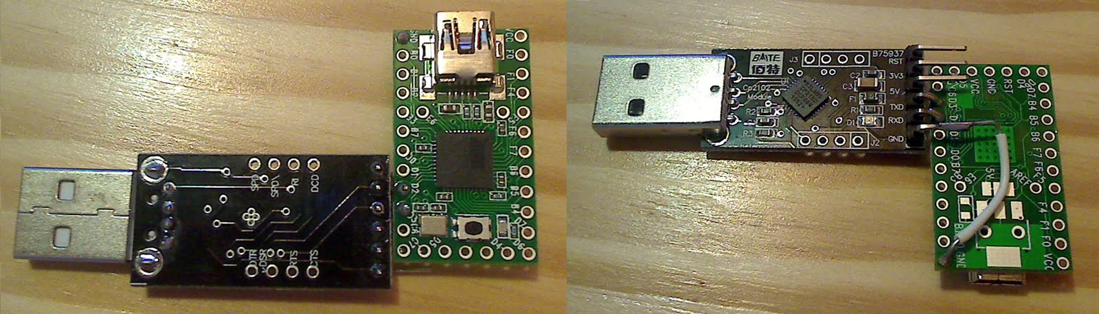
| − | The example below shows how to connect a CP2102 converter (left) to a Teensy 2.0 board (right): | + | The example below shows how to connect a (mislabeled) CP2102 converter (left) to a Teensy 2.0 board (right): |
| | | | |
| | <!--T:15--> | | <!--T:15--> |
| − | <div class="image200px">[http://gimx.fr/img/screenshots/PC-to-PS3-USB-controller.JPG http://gimx.fr/img/screenshots/PC-to-PS3-USB-controller.JPG]</div> | + | <div class="image200px">[https://gimx.fr/img/screenshots/PC-to-PS3-USB-controller.JPG https://gimx.fr/img/screenshots/PC-to-PS3-USB-controller.JPG]</div> |
| | | | |
| | <!--T:16--> | | <!--T:16--> |
| Line 129: |
Line 103: |
| | | | |
| | <!--T:17--> | | <!--T:17--> |
| − | <div class="image200px">[http://gimx.fr/img/adapter/solderless.jpg http://gimx.fr/img/adapter/solderless.jpg]</div> | + | <div class="image200px">[https://gimx.fr/img/adapter/solderless.jpg https://gimx.fr/img/adapter/solderless.jpg]</div> |
| | | | |
| | <!--T:19--> | | <!--T:19--> |
| | Examples: | | Examples: |
| | * Bumble-b and FT232RL wired on a breadboard: | | * Bumble-b and FT232RL wired on a breadboard: |
| − | :<div class="image200px">[http://gimx.fr/img/screenshots/ft232rl_bumbleb.jpg http://gimx.fr/img/screenshots/ft232rl_bumbleb.jpg]</div> | + | :<div class="image200px">[https://gimx.fr/img/screenshots/ft232rl_bumbleb.jpg https://gimx.fr/img/screenshots/ft232rl_bumbleb.jpg]</div> |
| | * Teensy++ and CP2102 wired on a breadboard: | | * Teensy++ and CP2102 wired on a breadboard: |
| − | :<div class="image200px">[http://gimx.fr/img/screenshots/cp2102_teensy++.jpg http://gimx.fr/img/screenshots/cp2102_teensy++.jpg]</div> | + | :<div class="image200px">[https://gimx.fr/img/screenshots/cp2102_teensy++.jpg https://gimx.fr/img/screenshots/cp2102_teensy++.jpg]</div> |
| | * Teensy 2.0 and CP2102 soldered: | | * Teensy 2.0 and CP2102 soldered: |
| − | :<div class="image200px">[http://gimx.fr/img/adapter/soldered.jpg http://gimx.fr/img/adapter/soldered.jpg]</div> | + | :<div class="image200px">[https://gimx.fr/img/adapter/soldered.jpg https://gimx.fr/img/adapter/soldered.jpg]</div> |
| | + | |
| | + | ==Firmware loading== <!--T:8--> |
| | + | |
| | + | <!--T:9--> |
| | + | *[http://gimx.fr/download/gimx-firmwares Firmwares] |
| | + | {{Firmwares/en}} |
| | + | |
| | + | ===Teensy boards=== <!--T:24--> |
| | + | |
| | + | <!--T:25--> |
| | + | Teensy boards can be easily flashed using the [http://www.pjrc.com/teensy/loader.html Teensy Loader].<br /> |
| | + | It is probably the easier to use flashing tool, but it is only compatible with '''genuine''' teensy boards. |
| | + | |
| | + | ===Cheap Arduino-compatible atmega32u4-based boards=== <!--T:26--> |
| | + | |
| | + | ====Using the Arduino Builder tool==== <!--T:27--> |
| | + | |
| | + | <!--T:28--> |
| | + | * The order of operations must be followed strictly, as Arduino builder is quite finicky! |
| | + | * Download the Arduino Leonardo drivers and save them into the same folder: |
| | + | ** [https://github.com/arduino/Arduino/raw/master/build/windows/dist/drivers/arduino.cat arduino.cat] |
| | + | ** [https://github.com/arduino/Arduino/raw/master/build/windows/dist/drivers/arduino.inf arduino.inf] |
| | + | * Right-click on the arduino.inf file and click on Install. |
| | + | * Make sure that the USB to UART board (e.g. CP2102) is connected and powered, and that the wiring with the atmega32u4 board is correct. |
| | + | * Make sure that the atmega32u4 board is connected and powered. |
| | + | * Download the [http://sourceforge.net/projects/arduinodev/files/ArduinoBuilder/ArduinoBuilder-0.9.1.7z/download Arduino Builder tool] and extract the archive (using [http://www.7-zip.org/ 7zip]). |
| | + | * Run ArduinoBuilder.exe. |
| | + | * Click on "Load Sketch / HEX", and select the desired atmega32u4.hex firmware. |
| | + | * Click on "Board Type" and select "Arduino Leonardo". |
| | + | * Click on the COM port that matches the "Silicon Labs CP210x ... (COMX)" COM port in the device manager (or whatever the name of your USB to UART board is). This is a trick to make the Arduino Builder tool look for a new COM port. If no COM port is visible, make sure the USB adapter AND the Arduino are plugged into two separate USB ports on the PC, then close and reopen Arduino Builder. |
| | + | * The following message should appear: "Forcing reset using 1200bps open/close on COMX...". |
| | + | * Quickly unplug/replug the atmega32u4 board, or connect RST to GND twice. |
| | + | * The atmega32u4 board should run the bootloader. The Arduino builder tool should find the Arduino Leonardo COM port and flash the firmware. |
| | + | Upon success a "Uploading completed!" message should be displayed.<br /> |
| | + | |
| | + | ====Using Avrdude==== <!--T:29--> |
| | + | |
| | + | <!--T:30--> |
| | + | * Download the Arduino Leonardo drivers and save them into the same folder: |
| | + | ** [https://github.com/arduino/Arduino/raw/master/build/windows/dist/drivers/arduino.cat arduino.cat] |
| | + | ** [https://github.com/arduino/Arduino/raw/master/build/windows/dist/drivers/arduino.inf arduino.inf] |
| | + | * Right-click on the arduino.inf file and click on Install. |
| | + | * Make sure that the USB to UART board (e.g. CP2102) is connected and powered, and that the wiring with the atmega32u4 board is correct (see above GND->GND, TXD->RXD, RXD->TXD). |
| | + | * Make sure that the atmega32u4 board is connected to your PC and powered. |
| | + | * You should now have the atmega32u4 board connected via the USB-to-UART ''and'' via its on-board USB port |
| | + | * Download the [http://sourceforge.net/projects/arduinodev/files/ArduinoBuilder/ArduinoBuilder-0.9.1.7z/download Arduino Builder tool] and extract the archive (using [http://www.7-zip.org/ 7zip]). |
| | + | * Open a command window (cmd) and change the current directory to the extracted ArduinoBuilder folder. e.g. cd "C:\Path\To\ArduinoBuilder\", or simply shift-right-click in windows file explorer and click "open command window here." |
| | + | * Type the following text but don't press enter: |
| | + | avrdude -p atmega32u4 -c avr109 -P COMx -D -U flash:w:<path to atmega32u4.hex>:i |
| | + | * Make sure to replace "<path to atmega32u4.hex>" in the command line with the location of the firmware to load (for example: C:\Users\YourUserName\Downloads\firmwares-5.0\EMUPS4\atmega32u4.hex). |
| | + | * Open the device manager, and expand the "Ports" item. You should see your USB-to-UART driver (e.g. CP2102) connected to a COM port and the Arduino connected to another COM port. *Neither* of these are the COM ports you're looking for, in all likelihood. |
| | + | * Unplug/replug the atmega32u4 on-board USB (''not'' the USB-to-UART) from your PC (doing this on the PC side rather than the Arduino side may be easier). When you replug it back in, watch the device manager, and notice which COM port is opened when the bootloader starts up. Ideally, this will be the same every time it is disconnected and reconnected. *THIS* is the COM port you want! |
| | + | * Change the "x" in "COMx" in the above command to the number of the COM port that the bootloader uses. |
| | + | * Unplug and replug the atmega32u4 USB again, and as soon the bootloader COM shows up, press enter to execute your command |
| | + | * The bootloader is executed very briefly. You may have to make a few attempts before the firmware gets loaded correctly! |
| | + | * If successful, avrdude should say "avrdude done. Thank you." |
| | + | |
| | + | <!--T:31--> |
| | + | In GNU/Linux, the avrdude command is: |
| | + | avrdude -p atmega32u4 -c avr109 -P /dev/ttyACM0 -D -U flash:w:atmega32u4.hex:i |
| | + | (make sure to adjust the port and the file) |
| | + | |
| | + | ===Other tools=== <!--T:32--> |
| | + | |
| | + | <!--T:10--> |
| | + | There are a few other tools that can be used to load the hex file: |
| | + | * [http://www.atmel.com/tools/FLIP.aspx Flip utility from Atmel] (not compatible with genuine teensy boards and with Arduino-compatible atmega32u4-based boards) |
| | + | * [http://dfu-programmer.sourceforge.net/ dfu-programmer command-line tool] (not compatible with genuine teensy boards and with Arduino-compatible atmega32u4-based boards) |
| | + | |
| | + | <!--T:11--> |
| | + | dfu-programmer example: |
| | + | sudo dfu-programmer at90usb162 erase |
| | + | sudo dfu-programmer at90usb162 flash at90usb162.hex |
| | + | sudo dfu-programmer at90usb162 reset |
| | + | |
| | + | ==Serial port settings== <!--T:33--> |
| | + | |
| | + | <!--T:34--> |
| | + | On Windows the driver for FTDI chips (e.g. FT232R, FT230X, FT231X...) provides a "Latency Timer" setting than should be set to 1ms for optimal performance.<br /> |
| | + | The procedure is detailed on the FTDI website: [http://www.ftdichip.com/Support/Knowledgebase/index.html?cdmcomportadvancedproperti.htm link]. |
| | | | |
| − | ==Connection== <!--T:20--> | + | ==Next Tutorial== <!--T:20--> |
| | | | |
| | <!--T:21--> | | <!--T:21--> |
| − | If it's not already done, install [http://gimx.fr/downloads GIMX].<br />
| |
| − | Connect the USB to UART converter to your PC, and connect the usb dev board to your console.<br />
| |
| − | Turn the console on (the ps/guide buttons are not working at this point).<br />
| |
| − | The console should detect a controller (if you add another controller, it should be detected as controller #2).<br />
| |
| − | Start gimx-launcher:<br />
| |
| − | TODO: update screenshot<br />
| |
| − | <div class="image200px">[http://gimx.fr/img/screenshots/tuto/2.4_2_gimx-serial.png http://gimx.fr/img/screenshots/tuto/2.4_2_gimx-serial.png]</div>
| |
| − | In Ubuntu/Linux, the USB to UART converter should be detected as "ttyUSBX" (with 'X' a number).<br />
| |
| − | In Windows, it should be detected as "COMX" (with 'X' a number). Check the device manager to select the right one.
| |
| − | <div class="image200px">[http://gimx.fr/img/screenshots/WinCP2102.gif http://gimx.fr/img/screenshots/WinCP2102.gif]</div>
| |
| | Now that your adapter is ready you can follow the instructions on the [[Quick_Start|Quick Start page]]. | | Now that your adapter is ready you can follow the instructions on the [[Quick_Start|Quick Start page]]. |
| | </translate> | | </translate> |
This page explains how to build a GIMX DIY USB adapter.
Buy a ready to use GIMX adapter from the official GIMX shop.
A much easier but less complete tutorial is also available: DIY USB Adapter for dummies.
A German translation of a previous version is also available on the forum: old German translation.
Warning: you are responsible for the hardware you buy, and anything right or wrong you do with this.
Required hardware parts
USB to serial TTL converter
Make sure it works at 500kbps and that it is 5V tolerant.
| chip |
CP2102 |
FT232R |
PL2303HX |
CH340 |
FT230X
|
| 5V tolerant
|
yes
|
(1)
|
(1)
|
(1)
|
yes
|
| 500 kbps
|
yes
|
yes
|
(2)
|
no
|
yes
|
|
|
| compatible
|
yes
|
(1)
|
(1)(2)
|
no
|
yes
|
(1) depends on the board
(2) only on Linux
Examples:
AVR USB development board
Make sure it is working at 5V and that is has a chip among the following: at90usb82, at90usb162, at90usb646, at90usb647, at90usb1286, at90usb1287, atmega16u2, atmega32u2, atmega16u4, atmega32u4
Examples:
Recommended setup
- CP2102 converter from ebay (very low price, but sometimes low delivery)
- Teensy 2.0 board (low price, good quality, and quick delivery).
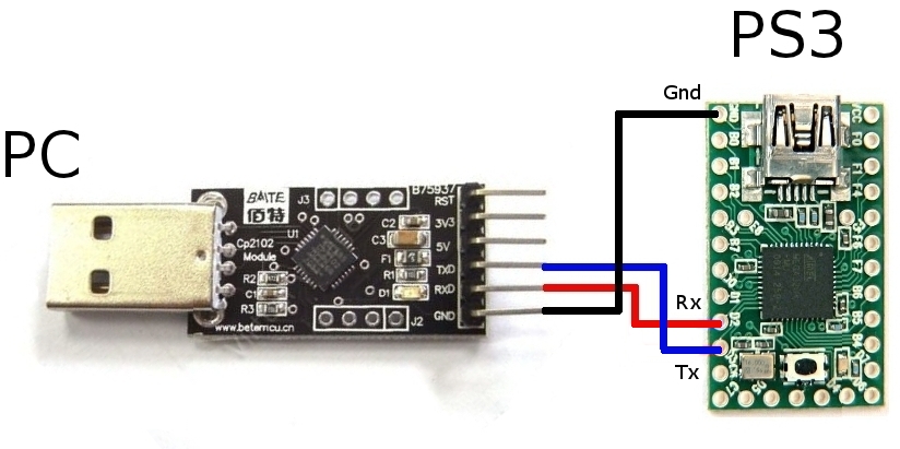
Wiring
The only thing you have to do is to connect the following pins:
| USB dev board |
USB to UART board
|
| GND |
GND
|
| RX |
TX / TXO / TXD
|
| TX |
RX / RXI / RXD
|
Warning: some adapters are mislabeled and have inverted RX/TX.
With a Teensy 2.0 or Arduino Leonardo as a USB dev board:
| Arduino Leonardo |
Teensy 2.0 |
USB to UART board
|
| GND |
GND |
GND
|
| 0 (RX1) |
D2 |
TX / TXO / TXD
|
| 1 (TX1) |
D3 |
RX / RXI / RXD
|
If you use the arduino on-board USB to serial converter, Rx and Tx are inverted, i.e. Rx = TX▶ and Tx = RX◀
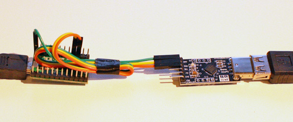
The example below shows how to connect a (mislabeled) CP2102 converter (left) to a Teensy 2.0 board (right):
It's possible to solder wires or to use jumper wires (these are generally provided with USB to serial TTL boards) in case your AVR USB board has header pins:
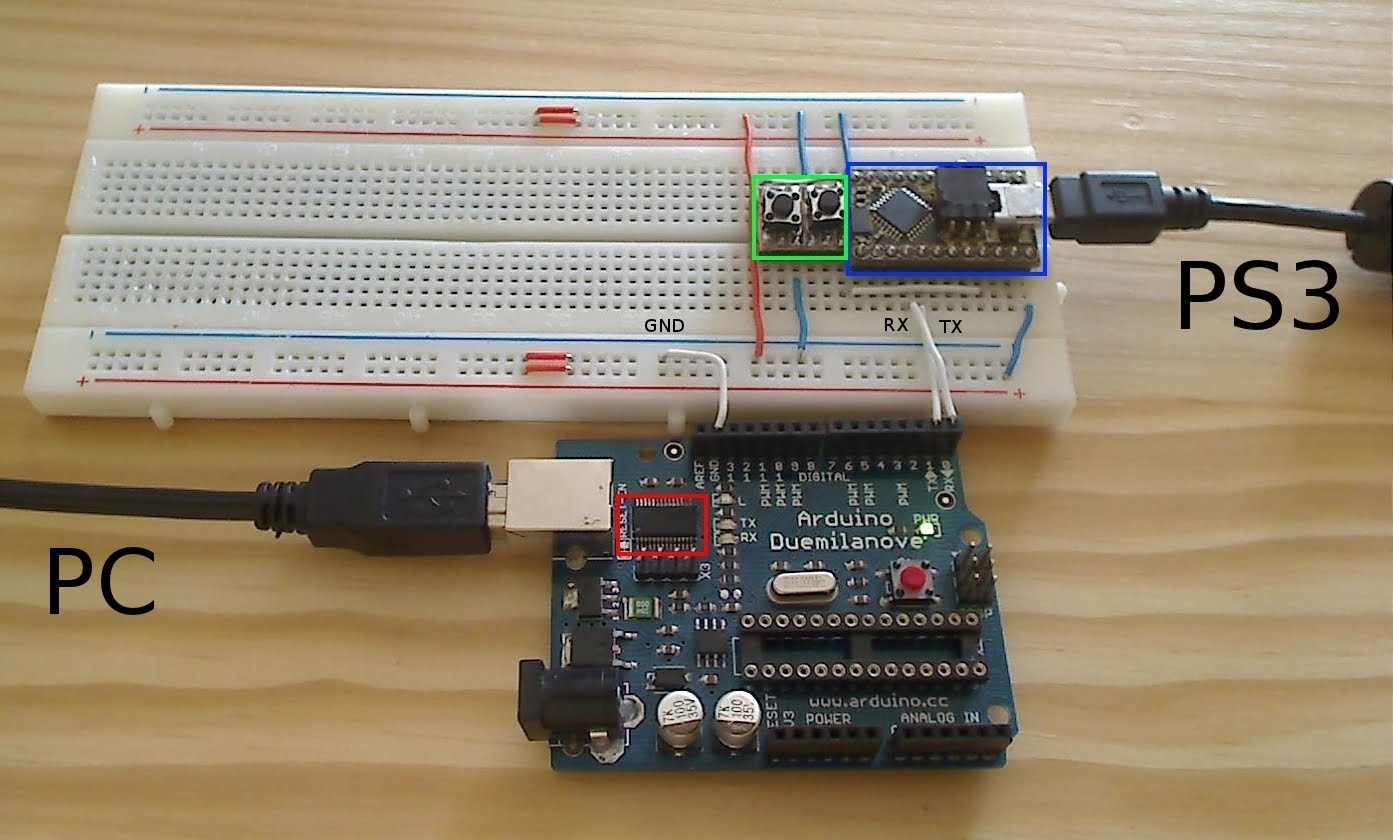
Examples:
- Bumble-b and FT232RL wired on a breadboard:
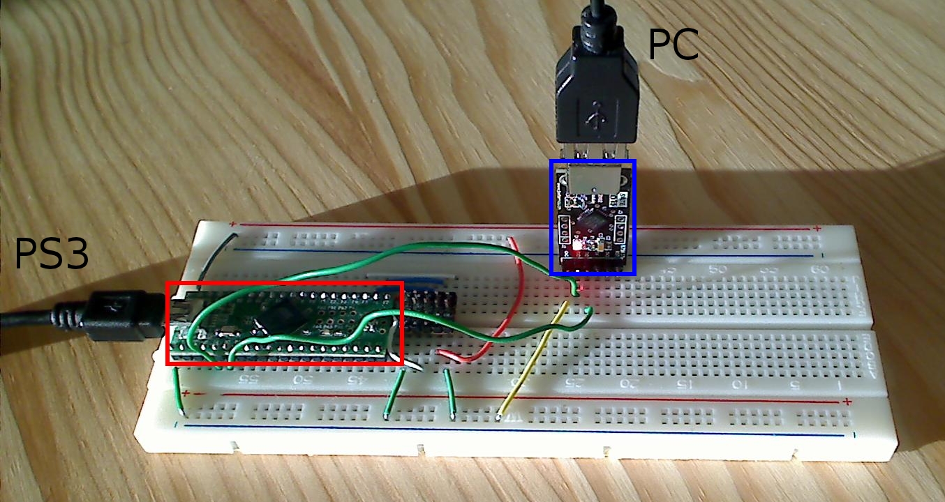
- Teensy++ and CP2102 wired on a breadboard:
- Teensy 2.0 and CP2102 soldered:
Firmware loading
- EMUJOYSTICKPS3: HID joystick emulation, with 16bit stick axes, for PS3
- EMUPS3: Sixaxis emulation, for PS3
- EMU360: 360 pad emulation, for Xbox 360
- EMUPS4: Hori Pad FPS Plus emulation, for PS4 (with touchpad support)
- EMUXONE: Xbox One pad emulation, for Xbox One
- EMUG29PS4: Logitech G29 gaming wheel emulation, for PS4, with force feedback support
- EMUG27PS3: Logitech G27 gaming wheel emulation, for PS3, with force feedback support
- EMUGTFPS2: Logitech GT Force emulation, for PS2, with force feedback support
- EMUDFPS2: Logitech Driving Force emulation, for PS2, with force feedback support
- EMUDFPPS2: Logitech Driving Force Pro emulation, for PS2, with force feedback support
- EMUG27PC: Logitech G27 gaming wheel emulation, for PC, force feedback support
Teensy boards
Teensy boards can be easily flashed using the Teensy Loader.
It is probably the easier to use flashing tool, but it is only compatible with genuine teensy boards.
Cheap Arduino-compatible atmega32u4-based boards
Using the Arduino Builder tool
- The order of operations must be followed strictly, as Arduino builder is quite finicky!
- Download the Arduino Leonardo drivers and save them into the same folder:
- Right-click on the arduino.inf file and click on Install.
- Make sure that the USB to UART board (e.g. CP2102) is connected and powered, and that the wiring with the atmega32u4 board is correct.
- Make sure that the atmega32u4 board is connected and powered.
- Download the Arduino Builder tool and extract the archive (using 7zip).
- Run ArduinoBuilder.exe.
- Click on "Load Sketch / HEX", and select the desired atmega32u4.hex firmware.
- Click on "Board Type" and select "Arduino Leonardo".
- Click on the COM port that matches the "Silicon Labs CP210x ... (COMX)" COM port in the device manager (or whatever the name of your USB to UART board is). This is a trick to make the Arduino Builder tool look for a new COM port. If no COM port is visible, make sure the USB adapter AND the Arduino are plugged into two separate USB ports on the PC, then close and reopen Arduino Builder.
- The following message should appear: "Forcing reset using 1200bps open/close on COMX...".
- Quickly unplug/replug the atmega32u4 board, or connect RST to GND twice.
- The atmega32u4 board should run the bootloader. The Arduino builder tool should find the Arduino Leonardo COM port and flash the firmware.
Upon success a "Uploading completed!" message should be displayed.
Using Avrdude
- Download the Arduino Leonardo drivers and save them into the same folder:
- Right-click on the arduino.inf file and click on Install.
- Make sure that the USB to UART board (e.g. CP2102) is connected and powered, and that the wiring with the atmega32u4 board is correct (see above GND->GND, TXD->RXD, RXD->TXD).
- Make sure that the atmega32u4 board is connected to your PC and powered.
- You should now have the atmega32u4 board connected via the USB-to-UART and via its on-board USB port
- Download the Arduino Builder tool and extract the archive (using 7zip).
- Open a command window (cmd) and change the current directory to the extracted ArduinoBuilder folder. e.g. cd "C:\Path\To\ArduinoBuilder\", or simply shift-right-click in windows file explorer and click "open command window here."
- Type the following text but don't press enter:
avrdude -p atmega32u4 -c avr109 -P COMx -D -U flash:w:<path to atmega32u4.hex>:i
- Make sure to replace "<path to atmega32u4.hex>" in the command line with the location of the firmware to load (for example: C:\Users\YourUserName\Downloads\firmwares-5.0\EMUPS4\atmega32u4.hex).
- Open the device manager, and expand the "Ports" item. You should see your USB-to-UART driver (e.g. CP2102) connected to a COM port and the Arduino connected to another COM port. *Neither* of these are the COM ports you're looking for, in all likelihood.
- Unplug/replug the atmega32u4 on-board USB (not the USB-to-UART) from your PC (doing this on the PC side rather than the Arduino side may be easier). When you replug it back in, watch the device manager, and notice which COM port is opened when the bootloader starts up. Ideally, this will be the same every time it is disconnected and reconnected. *THIS* is the COM port you want!
- Change the "x" in "COMx" in the above command to the number of the COM port that the bootloader uses.
- Unplug and replug the atmega32u4 USB again, and as soon the bootloader COM shows up, press enter to execute your command
- The bootloader is executed very briefly. You may have to make a few attempts before the firmware gets loaded correctly!
- If successful, avrdude should say "avrdude done. Thank you."
In GNU/Linux, the avrdude command is:
avrdude -p atmega32u4 -c avr109 -P /dev/ttyACM0 -D -U flash:w:atmega32u4.hex:i
(make sure to adjust the port and the file)
Other tools
There are a few other tools that can be used to load the hex file:
dfu-programmer example:
   sudo dfu-programmer at90usb162 erase
   sudo dfu-programmer at90usb162 flash at90usb162.hex
   sudo dfu-programmer at90usb162 reset
Serial port settings
On Windows the driver for FTDI chips (e.g. FT232R, FT230X, FT231X...) provides a "Latency Timer" setting than should be set to 1ms for optimal performance.
The procedure is detailed on the FTDI website: link.
Next Tutorial
Now that your adapter is ready you can follow the instructions on the Quick Start page.