Latest revision as of 12:31, 10 March 2016
Information about message (contribute ) This message has no documentation.
If you know where or how this message is used, you can help other translators by adding documentation to this message.
Message definition (RPi )
The on-board UART runs at 0V/3.3V levels, and the AVR USB board has to run at 5V to operate at 16MHz (running at 3.3V would only allow to operate at 8MHz).<br />
The on-board UART runs at 0V/3.3V levels, and the AVR USB board has to run at 5V to operate at 16MHz (running at 3.3V would only allow to operate at 8MHz).<br />
Connecting the RPi and the AVR USB board directly may damage the hardware!<br />
One cheap solution is to use a voltage divider:<br />
* Connect both GNDs
* It's safe to connect the TXD pin of the RPi to the Rx pin of the AVR USB board (the GIMX firmwares configure the Rx pin as an input)
* To connect the Tx pin of the AVR USB board to the RXD pin of the RPi, you'll need to convert the voltage level from 0..5V to 0..3.3V.<br />
This can be done with a simple resistive divider:
<div class="image200px">[https://gimx.fr/img/wiki/Resistive_divider.png https://gimx.fr/img/wiki/Resistive_divider.png]</div>
Vin is the Tx pin of the AVR USB board, Vout is the RXD pin of the RPi, R1=2.2kΩ , R2=3.3kΩ
* Do not connect any other pin!
Translation L'interface série fonctionne aux niveaux 0V/3.3V, alors que la carte AVR USB doit être alimentée à 5V pour fonctionner à 16MHz (à 3.3V elle ne peut fonctionner qu'à 8MHz).<br /> L'interface série fonctionne aux niveaux 0V/3.3V, alors que la carte AVR USB doit être alimentée à 5V pour fonctionner à 16MHz (à 3.3V elle ne peut fonctionner qu'à 8MHz).
Connecter les broches GND.
Il est sans danger de connecter la broche TXD du RPi à la broche RX de la carte AVR USB (le firmware GIMX configure la broche RX comme une entrée).
Pour connecter la broche TX de la carte AVR USB à la broche RXD du RPi, il faut convertir les niveaux de tension de 0..5V à 0..3.3V. Ceci peut se faire simplement à l'aide d'un diviseur de tension :
Vin est la broche TX de la carte AVR USB, Vout est la broche RXD du RPi, R1=2.2kΩ , R2=3.3kΩ
Ne connecter aucune autre broche ! 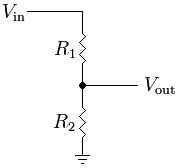